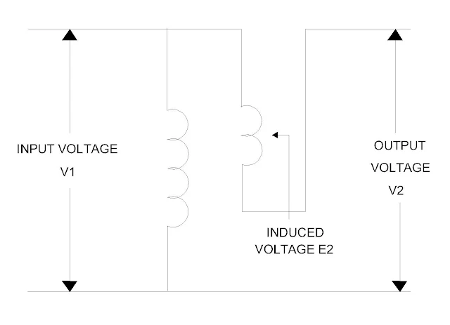
- When the load on the supply system is changed, the voltage at the consumers’ terminal also is changed.
- The voltage control is necessary in order to keep the voltage variation within certain limits for reliable service to the consumers.
- The study of single phase induction regulator is explained here.
Principle
- The working principle of the single phase induction regulator is similar to that of the three phase induction motor.
Construction
- The single phase induction regulator consists of primary winding ( stator ) and secondary winding ( rotor ).
- The secondary winding is connected is in series with the line whose voltage is controlled.
- The rotor doesn’t allow to rotate continuously but its position can be adjusted by means of a small motor or worm gear.
- When the position of the secondary winding is changed with respect to primary winding, the injected voltage in the line also is changed.
Working
- When a supply voltage is given to the primary winding, an alternating flux Фm produced in it which cuts the rotor winding.
- The induced emf in the rotor winding is due to interaction of rotating flux and stationary rotor.
- The magnitude of the rotor emf depends upon position of rotor with respect to stator.
Position of rotor
The initial position of rotor is shown in
the Figure A.
Boost voltage
- When the rotor rotates at angle 90 degree in the clockwise direction, the rate of change of flux linkage in the rotor is maximum therefore it produces maximum emf in this direction.
- It is called boost condition. It is shown in the Figure ( B )
Zero voltage
- When a rotor rotates in the clockwise direction by 1800, the rate of change of flux linkage becomes zero therefore there is no induced emf in the secondary winding therefore the primary voltage is equal to secondary voltage.
Buck voltage
- When a rotor rotates in the clockwise direction by 2700 from its initial position, the rate of change of flux linkage maximum but it is in the opposite direction therefore the secondary induced emf is in opposite direction to that of primary voltage.
- It is called as buck condition.
The magnitude of the induced emf depends
upon the sine of angle between two winding axes.
Induced voltage α Sin ( angle between two
axes )
Equivalent circuit
- The equivalent circuit of the single-phase induction regulator is shown in the Figure B by neglecting magnetizing circuit. Let
V1 = Supply voltage
E2 = Induced emf
V2 = Output voltage
I1 = Supply voltage
I2 = Load current
Rating
- The rating of the induction regulator is the product of its full load current, voltage boost and number of phases.
Advantages
- It provides constant voltage at load side under varying load conditions
- It finds widespread application in the high voltage laboratories.
Disadvantages
- High cost
- Careful design is necessary in order to avoid waveform distortion
- It produces noise due to vibration.
You may also like :
Effect of harmonics on power factor
What is current harmonics and voltage
harmonics?
How to reduce mitigation of third
harmonic?


No comments:
Post a Comment