Featured post

Estimation of Energy Storage Requirement by 2032

Energy storage requirement for Solar PV connected to grid In this post, energy storage requirement in India by 2032 is given here. The ESS r...

Showing posts with label Transmission line. Show all posts

22/04/2022

Two Port Networks are in Tandem or Series

Tandem ( Series ) Connection of Two Port Network

  • Two networks are connected in series such that output of one network is connected to input of another network, such type of connection is called as Tandem connection of two port network. 
  • It is considered that network 1 is connected to network 2 in tandem. 

17/04/2022

Important Formulas : ABCD Parameters of Transmission Line

ABCD Parameters of Transmission Lines

Important formula of ABCD ( Two Port ) Network of Transmission Line for short transmission line, medium transmission line, long transmission line, parallel network and series network is given here.

ABCD Parameters: Short Transmission Line

A = 1

B = Z

C = 0 and

D = 1

ABCD Parameters: Medium Transmission Line -  Nominal T Method

A = ( 1 + YZ/2 )  

B = Z( 1 + YZ/4 )

C = Y and

D = 1 + YZ/2

ABCD Parameters: Medium Transmission Line - Nominal π Method

A = ( 1 + YZ/2 )  

B = Z

C =  Y ( 1 + YZ/4 ) and

D = 1 + ( YZ / 2 )  

ABCD Parameters: Long Transmission Line

A = Cos h √ YZ

B = ZC Sin h √ YZ

C = Sin h √ YZ / ZC

D = Cos h √ YZ


You may also like to read these articles :

What is blue hydrogen?

What is green hydrogen?

Microphone transformer

India’s Renewable Energy Generation

Types of Resolver


ABCD Parameters: Parallel network

A = {A1B2 + A2B1 / B1 + B2 }

B = ( B1B2 / B1 + B2 )

C = { ( C1 + C2 ) – ( D1 – D2 )( A1 – A2 ) / ( B1 + B2 ) }

D = { B1D2 + B2D1 / ( B1 + B2 )}

ABCD Parameters: Series network

A = A1A2 + B1C2

B = A1B2 + B1D2

C = A2C1 + C2D1

D = B2C1 + D1D2


15/04/2022

ABCD Parameters of Two Parallel Transmission Line

Two Parallel Transmission Line

Let us consider that the two-transmission line or network is in parallel. As two transmission lines are parallel, sending end voltage and receiving end voltage for both transmission line is equal however current through both transmission lines is different. In this theory, we find out equivalent A, B, C and D parameters of parallel networks or transmission line.

ABCD Parameters of Long Transmission Line

Analysis of Long Transmission Line ( Rigorous Method of Solution of Long Transmission Line )

Long transmission line

A long transmission line is considered as infinite length. It is not possible to calculate all the parameters for infinite long length therefore here we consider only small length dx in order to evaluate whole line. Let us consider that length of line is dx at x distance from receiving end of the transmission line.

13/04/2022

ABCD Parameters of Nominal π method

Medium Transmission Line: Nominal π method

The total capacitance of the transmission line is divided into two parts, half at the sending end side and another half at the receiving end side in the nominal π method. All the parameters are given considering three phase transmission line.

11/04/2022

ABCD Parameters of Nominal T method

Medium Transmission Line: Nominal T Method

The total capacitance of the transmission line is considered at the middle of the line in the nominal T method, considering half the impedance at the sending end side and another half at the receiving end side. All the parameters are given considering three phase transmission line.

ABCD Parameters of End Condenser Method

Long Transmission Line: End Condenser Method

The total capacitance of the transmission line is considered at the receiving end side or load side in the medium transmission line. All the parameters are given considering three phase transmission line.

Here

VS = Sending end voltage to neutral

VR = Receiving end voltage to neutral

09/04/2022

ABCD Parameters of Short Transmission Line

Short transmission line

The shunt capacitance and shunt conductance are neglected therefore only resistance and reactance is shown in the short transmission line. All the parameters are given considering three phase transmission line.

ABCD Parameters of Transmission Line

ABCD Parameters

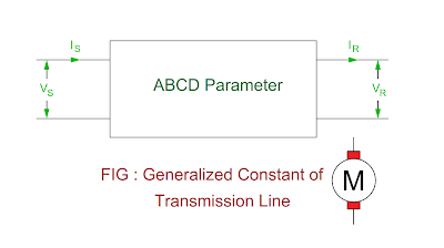
The ABCD parameters of generalized constant of the transmission line is find out by sending end current and sending end voltage equation. In order to find out ABCD parameters of the transmission line, it is considered that (1) The receiving end of the transmission line is open circuited and (2) Receiving end of the transmission line is short circuited.

ABCD-parameter-of-transmisison-line.png

VS = AVR + BIR

IS = CVR + DIR

Where

VS = Sending end voltage

IS = Sending end current

VR = Receiving end voltage

IR = Receiving end current

A, B, C and D = Constant

The generalized constant of the transmission line is found out by

Receiving end of the transmission line open circuited, receiving end current IR = 0

ABCD Parameters: Receiving End Open Circuited

Constant A

VS = AVR

A = VS / VR and

The constant A is defined as the ratio of sending end voltage to the receiving end voltage when receiving end of the line is open circuited. It is also called as reverse voltage gain. It is unitless.

Constant C

IS = CVR

C = IS / VR

The constant C is defined as the ratio of sending end current to the receiving end voltage when receiving end of the line is open circuited. Its unit is 1 / ohm or mho.


You may also like to read these articles :

What is blue hydrogen?

What is green hydrogen?

Microphone transformer

India’s Renewable Energy Generation

Types of Resolver


Receiving end of the transmission line is short circuited, when receiving end voltage VR = 0

ABCD Parameters: Receiving End Short Circuited

Constant B

VS = BIR

B = VS / IR

The constant B is defined as the ratio of sending end voltage to the receiving end current when receiving end of the transmission line is short circuited. Its unit is ohm.

Constant D

IS = DIR

D = IS / IR

The constant D is defined as the ratio of sending end current to the receiving end current when receiving end of the transmission line is short circuited. It is also called as reverse current gain. It is unit less.

ABCD Parameters: Summary


Transmission line parameters

How to Find out?

Formula

Unit

Better known as

A

Receiving end of transmission line is open circuited

VS / VR

Unit less

Reverse voltage gain

B

Receiving end of transmission line is short circuited

VS / IR

ohm


C

Receiving end of transmission line is open circuited

IS / VR

mho


D

Receiving end of transmission line is short circuited

IS / IR

Unit less

Reverse current gain


02/04/2022

Corona Loss in the Transmission Line

Corona Loss

  • When alternating voltage across transmission is raised beyond a certain level, the conductors are surrounded by pale violet glow and smell of ozone gas. 
  • It is called as Corona effect on the transmission line.

05/03/2022

MWe and MWt in Electrical


Meaning of MWe and MWt

  • The MWe and MWt both values are referred for power plant. 
  • The MWe refers to electrical power output of the plant whereas MWt refers megawatt thermal input energy required. 

28/03/2021

Grading of Underground Cable

In this theory, the grading of cable or methods of uniform dielectric stress in the cable is given.

Grading of Cables

  • The process of achieving uniform dielectric stress in the cable is called as grading of cables. 
  • The dielectric stress is maximum at the center of the core and its value goes on decreasing as we move from center to sheath of cable. 
  • The dielectric stress in the cable is undesirable due to following reasons.

  1. The size of cable increases due to more thickness of insulation.
  2. There are possibilities of breakdown of insulation.

Methods of Grading of Cable

  • There are two methods for achieving uniform dielectric stress in the cable. It is known as grading of cable.

Capacitance Grading

  • The uniform dielectric stress in the cable is achieved by using layers of different dielectric, it is called as capacitance grading. 
  • The uniform dielectric stress in this method is achieved by using different layers of dielectric such that the permittivity εr of any layer is inversely proportional to the radius of distance from the center.

( εr ) α ( 1 / x )

( εr ) ( x ) = Constant ……. ( 1 )

Where x = Distance from center

Now potential gradient

 g = Q / 2πε0εrx

( g ) α Q / 2πε0 is also constant…. ( 2 )  ( ⸫ ( εr ) ( x ) = Constant )


capacitance-grading-of-cable.png


  • We can say that the value of dielectric stress at any point is constant and it is independent of distant from the center. 
  • The dielectric material having highest permittivity is used near the core and its value decreasing form core to the outer surface of cable. 
  • Let us consider that a cable is made of 3 layers of dielectric having outer diameter d1, d2 and D and relative permittivity εr1, εr2 and εr3 respectively.  
  • If the permittivity of dielectric materials are selected such that 

εr1 > εr2 > εr3

( εr1d1 ) = ( εr2d2 ) = ( εr3D ) 


Advantages of Capacitance Grading

  • The size of the graded cable is smaller than the non – graded cable for same safe potential.

       Potential difference across inner layer 


 V1 = { Q Loge ( d1 / d ) / 2πε0εr1 }

V1 = gmax d Loge ( d1 / d ) / 2         { ⸫ gmax d  / 2 = Q / 2πε0εr1 }             

Potential difference across centre layer

V2 = gmax d Loge ( d2 / d1 ) / 2              

Potential difference across outer layer

V3 = gmax d Loge ( D / d2 ) / 2    

Therefore, the potential difference between core and sheath is

V = V1 + V2 + V3  

       = gmax d Loge ( d1 / d ) / 2 + gmax d Loge ( d2 / d1 ) / 2  + gmax d Loge

                                                                                               ( D / d2 ) / 2

If the cable had homogenous permittivity, the potential difference between core and sheath is given by V’

       = gmax d Loge { ( d1 / d ) × ( d2 / d1 ) × ( D / d2 ) } / 2

 V’ = gmax d Loge { ( D / d ) } / 2

It should be noted that the potential of the graded cable ( V ) is more than the non – graded cable ( V’ ).

                                                 OR

We can say that the size of the graded cable is less than the non – graded cable for a given safe working voltage.      


Inter- sheath Grading

  • A homogenous dielectric material is used in this method of cable grading. 
  • The homogenous dielectric is divided into various layers by placing metallic inter-sheath between core and lead sheath. 
  • The inter-sheaths are held at constant potential whose value lies between core potential and earth potential.
  • Let us consider that the core diameter d, lead sheath diameter D and two inter-sheath of diameter d1 and d2 are inserted into homogenous dielectric at constant voltage.
  • Core diameter = d
  • Lead sheath diameter = D
  •  Voltage between core and inter-sheath = V1
  • Voltage between inter-sheath 1 and inter-sheath 2 = V2
  • Voltage between inter-sheath 2 and lead sheath = V3
  • As there is definite potential difference between inner and outer layers of each inter-sheath, we can say that each inter-sheath can be treated as single core cable.


intersheath-grading-of-cable.png

Maximum stress between core and inter-sheath1

g1max = V1 / ( d / 2 ) Log e ( d1 / d )

Maximum stress between inter-sheath1 and inter-sheath2

g2max = V2 / ( d1 / 2 ) Log e ( d2 / d1 )

Maximum stress between inter-sheath2 and lead sheath

g3max = V3 / ( d2 / 2 ) Log e ( D / d2 )

As the dielectric is homogeneous, the maximum stress in each layer is the same

g1max = g2max = g3max = gmax

V1 / ( d / 2 ) Log e ( d1 / d ) = V2 / ( d1 / 2 ) Log e ( d2 / d1 ) = V3 / ( d2 / 2 ) Log e ( D / d2 )

  • As the cable behaves like three capacitors in series, all the potentials are in phase. 
  • The voltage between conductor and earthed lead sheath is

        V = V1 + V2 + V3

Disadvantages of Inter-sheath Grading

  • It is not very easy to set sheath potentials.
  • The inter-sheath may be damaged due to transportation and installation.
  • There may be considerable inter – sheath losses due to charging current.

You may also like to read articles

Static AC Circuit Breaker

Static DC Circuit Breaker

Working of Light Dimmer Circuit

DC Time Delay Circuit

Comparison Between Three Phase Uncontrolled Rectifiers