In this article, details study of first order high
pass Butterworth filter, its frequency response, voltage gain, and second order
high pass Butterworth filter is given.
First order High Pass Butterworth Filter
- The high pass filter is obtained by changing frequency determining component – resistors and capacitors in the low pass filter.
- The first order high pass filter is obtained by interchanging R and C in the first order low pass filter.
- Figure shows first order high pass Butterworth filter.
Lower cut off frequency
- It is frequency at which gain of the amplifier reduces from maximum to 70.7% of its maximum value.
- It is from frequency response graph, one can say that lower cut off frequency is determining parameter for stop band frequencies and pass band frequencies.
Impedance of the
capacitor = – jXC
= –
j ( 1 / ωC )
= – j / 2πfC
= 1 / j2πfC
Input voltage at
point P according to voltage divider rule
VP = Vin
{ R / ( R – jXC ) }
= Vin {
R / ( R + 1 / j2πfC ) }
= Vin {
R / (( j2πfRC + 1) / j2πfC ) }
= Vin {
j2πfRC / ( 1 + j2πfRC ) }
Let us consider
that
Lower cut off frequency
fL = 1 / 2πRC
Divide numerator
and denominator by 1 /2πRC
= Vin {
( jf ) / ( 1 / 2πRC ) +( j2πfRC / 2πRC )
= Vin {
jf / ( 1 / fL + jf ) }
= Vin {
jf / ( 1 +jfL f ) / fL }
= Vin {
jf fL / ( 1 + jfL f ) }
Divide numerator
and denominator by fL2
= Vin {
j( f / fL ) / ( 1 + j( f / fL ) }
Output voltage Vo
= AF VP
Where AF = gain of the OP – Amp
= ( 1 + RF / R1 )
Output voltage Vo
= AF VP
= ( 1 + RF
/ R1 ) { j( f / fL ) / ( 1 + j( f / fL ) } Vin
Voltage Gain: Vo / Vin
= ( 1 + RF / R1 ) { j( f / fL ) / ( 1 + j( f /
fL ) }
Magnitude of Voltage Gain: ( 1 + RF
/ R1 ) { ( f / fL ) / ( 1 + √ ( f / fL )2
}
=
AF{ ( f / fL ) / ( 1 + √ ( f / fL )2
}
Frequency response of high pass Butterworth filter
- When the frequency decrease that of lower cut off frequency, the high pass Butterworth filter rolls at – 20 dB / dec.
- The voltage gain reduced to 0.707AF at lower cut off frequency.
- The voltage gain becomes constant when frequency increases beyond lower cut off frequency.
|
Frequency |
Voltage gain |
|
Low frequency |
< AF |
|
Lower cut off frequency |
= 0.707AF |
|
Greater than
lower cut off frequency |
Constant |
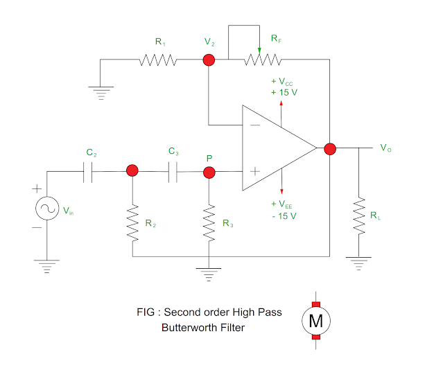
Second order High Pass Butterworth Filter
- The second order high pass Butterworth filter can be obtained by interchanging frequency determining components R & C in the second order low pass filter.
- The second order high pass Butterworth filter is shown in the Figure.

Magnitude of Voltage Gain: AF / √ { 1 + ( fL / f )2 }
Where
f = Input frequency
fL = Low cut off frequency
= 1 / 2π √ ( R2 ) ( R3 ) ( C2 ) ( C3 )
AF = Pass band gain
You may also like
:
Potential & Potential Difference


I liked your work and the way in which you have shared this article here about testing and tagging adelaide. It is a beneficial and helpful article for us. Thanks for sharing an article like this.
ReplyDelete