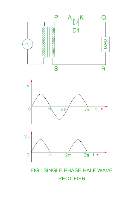
- As the rectifier conducts only during positive half cycle of the alternating supply, it is called as half wave rectifier.
- There is no current flows during negative half cycle of the alternating supply and the voltage across load is equal to supply voltage during positive half cycle and zero during negative half cycle.
Single Phase Half wave circuit description
- The AC supply to the diode is given through step down transformer.
- The anode of the diode is connected to P end of the transformer secondary winding whereas the cathode of the diode is connected to the Q end of the load.
- The step down transformer isolates rectifier circuit and AC supply system.
Operation
- The secondary winding of the transformer end P becomes positive with respect to S during positive half cycle of the alternating supply therefore the diode D1 conducts and load current passes through P – A – K – Q – LOAD – R – S.
- The voltage across load is equal to secondary voltage of the transformer neglecting voltage drop across diode.
- The secondary winding of the transformer end P becomes negative with respect to S during negative half cycle of the alternating supply therefore the diode D1 reverse biased, only leakage current passes through it.
- The voltage across load becomes zero during reverse biased condition of the diode.
- Therefore we can say that the current flows through load only during positive half cycle of the alternating supply.
- The output across load is not pure DC but it is called as pulsating ( AC + DC ).
Disadvantages
- As the output is pulsating therefore the filter circuit requires.
- Low output power
Ripple factor
- Ripple factor = RMS value of AC Component / DC Component
Ripple Factor For Half wave rectifier
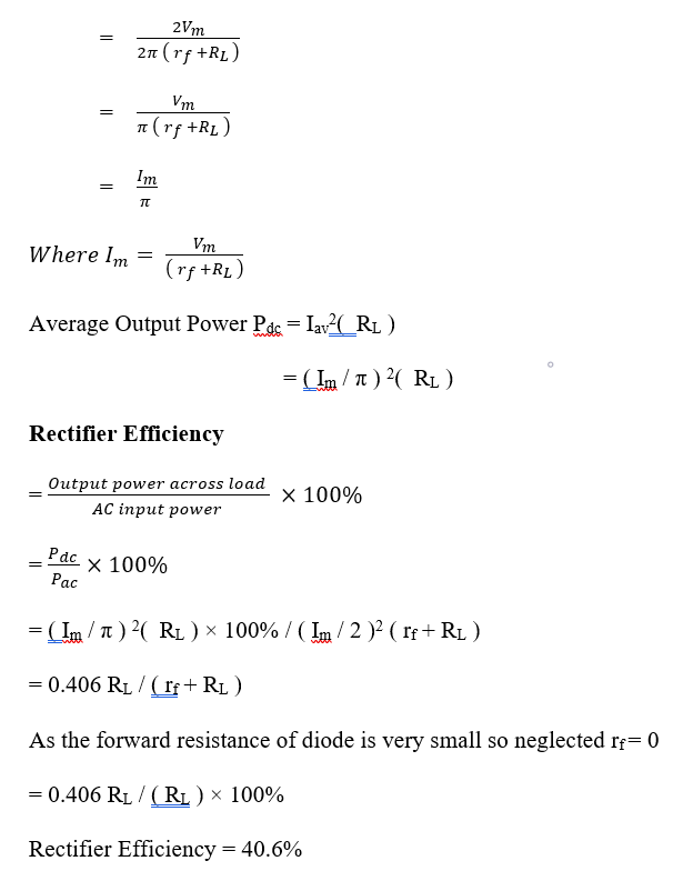
- IRMS = Im / 2
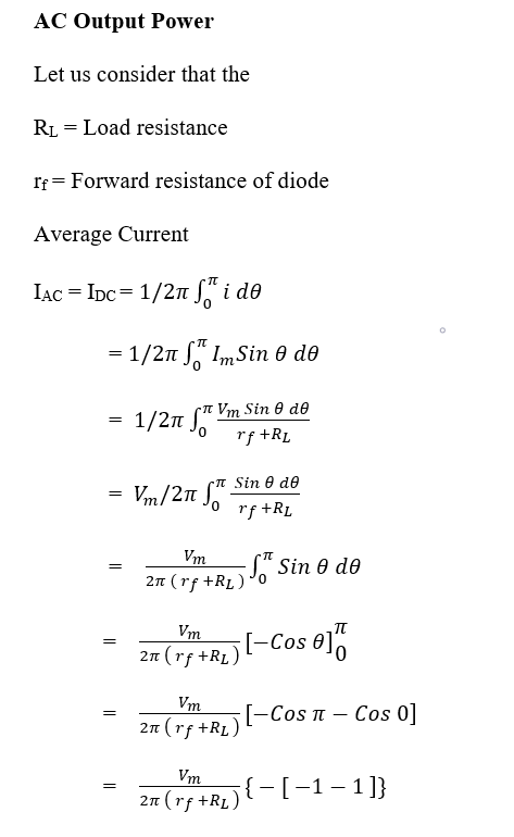
- IDC = Im / π
Therefore, the ripple factor for half wave
rectifier is
- Ripple factor = √ [ IRMS2 / IDC2 ] – 1
- Ripple factor = √ [ IMAX / 2 ]2 / [ IMAX / π ]2 – 1
=
√ [ π / 2 ]2 – 1
=
1.21
- The AC component exceeds than DC component in the output of the single phase half wave rectifier.
- The AC component is 121% than the DC
component.
Peak Inverse Voltage
- The PIV of the single phase rectifier is Vm ( voltage across secondary winding of the transformer )


No comments:
Post a Comment