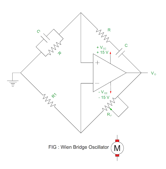
- The function of the Wien bridge oscillator is to generator sinusoidal frequency.
- It is audio frequency oscillator.
Circuit Connection
Diagram
- The Wien bridge circuit is connected between amplifier input and output terminal.
- This bridge has series RC circuit in one arm and parallel RC circuit in the other arm.
- The resistor R1 and RF is connected in the remaining arms. The total phase shift around the circuit must be 0 degree.
|
Feedback |
- The output of the operational amplifier is fed back to the both the inputs of the amplifier.
- One part of the feedback signal is connected to the inverting input ( negative ) terminal through feedback network R1 and RF.
- The function of this feedback network is to adjust amplifier gain into narrow limits.
- The series RC and parallel RC circuit forms second feedback circuit and it is fed back to the non – inverting input ( positive ) terminal from the output of the operational amplifier.
- The function of this feedback circuit is to rise oscillation.
|
RC Phase Shift Circuit Feedback |
- The series RC circuit is connected to parallel RC circuit.
- It is actually high pass filter ( Series RC circuit ) is connected to low pass filter ( Parallel RC circuit ).
- This band pass filter allows only selective frequency to pass.
Low frequency
- The reactance of the series capacitor is vey high so it acts like open circuit which blocks input signal therefore no output at low frequency.
High frequency
- The reactance of the parallel capacitor is very low, therefore Parallel RC circuit acts like short circuit across output therefore no output at high frequency.
Resonance frequency
- At resonance frequency, the circuit reactance is equal to resistance, the phase difference between input and output is equal to zero.
- The magnitude of the output voltage is 1/3 that of input voltage.
- The voltage gain of the amplifier must be equal to or greater than 3 for oscillation to start.
- The voltage gain ≥ 3 is set by feedback resistor R1 and RF.
- At resonance condition, the bridge becomes balance and at this time total phase shift become zero.
- If R = R1 = RF and C = C1 = C2 , the frequency of oscillation is equal to resonance frequency is given by
f = 1 / 2πRC
= 0.159 / RC
- The gain of the sustained oscillation is given by
Voltage Gain AV
= 1 / B
= 3
OR
1 + RF
/ R1 = 3
RF = 2R1
You
may also like :
What
do you mean by variable frequency drive?
Compare - Potential and Potential energy


No comments:
Post a Comment