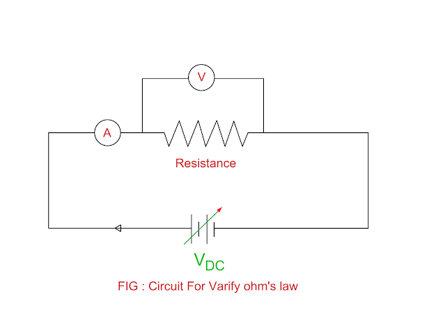
Apparatus
- DC Voltage Source : 1.0 V to 10.0 V
- Resistance
- DC voltmeter : Suitable range
- DC ammeter : Suitable range
- Multimeter
Circuit Diagram
Procedure
- Switch on the main supply.
- Set DC voltage at say 1.0 V , note down the reading of voltage and current.
- Increase DC voltage in step by step from 1.0 V to 5.0 V and note down reading of voltage and current.
Observation table
|
Sr.No |
Potential
Difference across resistor ( V ) |
Current
passes through resistor ( I ) |
Ratio of V to
I ( V / I ) |
|
1 |
1.0 |
0.1 |
10 |
|
2 |
2.0 |
0.2 |
10 |
|
3 |
3.0 |
0.3 |
10 |
|
4 |
4.0 |
0.4 |
10 |
|
5 |
5.0 |
0.5 |
10 |
- Observe the reading of voltage and current.
- If the voltage increases, current increases linearly.
- Calculate the ratio of V to I for each reading.
- Draw a graph for V ( Y – axis ) and I ( X – axis ).
Conclusion
- The electric current passes through conductor is directly proportional to potential difference across it.
- The ratio of V to I remains constant considering temperature and other consider unaltered.
You may also like
:
Potential and Potential
Energy
Majority Charge Carriers & Minority Charge Carriers


No comments:
Post a Comment