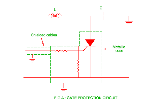
- There is possibility of false triggering due to over voltage across gate cathode junction of the SCR.
- The possibility of increase in the temperature of gate – cathode junction due to high current flows through it and this may result in damage of SCR.
- The gate circuit is protected against over voltage by placing suitable value of resistance in series with it.
- The voltage across SCR becomes very low and current through it very high when it is in turned on condition.
- This will result in production of magnetic field and collapse of electrical field.
Radio interference
- There is possibility of induce voltage across other SCR gate – cathode junction due to change in electrical field and magnetic field resulting turn on the SCR.
- There are other SCRs also turned on due to this malfunction. This effect of called as radio interference.
- Therefore it is necessary to protect SCR gate – cathode circuit.
- The gate circuit is protected by using shielded cable or twisted gate lead.
- The effect of false triggering is reduced due to flux does not pass through twisted cable.
 |
RF filter
-
The effect of radio
interference is reduced by using RF filter.
-
The RF filter is made by using
series inductor and parallel capacitor across the circuit.
-
The inductor
decreases the effect of di/dt effect of anode current and capacitor reduces the
effect of forward dv/dt voltage.
-
The calculation of inductor L and capacitor C
is done as below.
XL = RL
( Load resisance )
The effect of radio
interference is reduced by using RF filter.
The RF filter is made by using
series inductor and parallel capacitor across the circuit.
The inductor
decreases the effect of di/dt effect of anode current and capacitor reduces the
effect of forward dv/dt voltage.
The calculation of inductor L and capacitor C
is done as below.


No comments:
Post a Comment